- 您现在的位置:买卖IC网 > Sheet目录3818 > PIC18F4580-I/PT (Microchip Technology)IC PIC MCU FLASH 16KX16 44TQFP
2010 Microchip Technology Inc.
DS21801F-page 55
MCP2515
9.0
RESET
The MCP2515 differentiates between two resets:
1.
Hardware Reset – Low on RESET pin
2.
SPI Reset – Reset via SPI command
Both of these resets are functionally equivalent. It is
important to provide one of these two resets after
power-up to ensure that the logic and registers are in
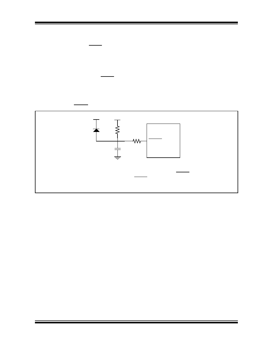
their default state. A hardware reset can be achieved
automatically by placing an RC on the RESET pin (see
Figure 9-1). The values must be such that the device is
held in reset for a minimum of 2 s after VDD reaches
operating voltage, as indicated in the electrical
specification (tRL).
FIGURE 9-1:
RESET PIN CONFIGURATION EXAMPLE
RESET
R1(2)
VDD
R
C
D(1)
Note 1: The diode D helps discharge the capacitor quickly when VDD powers down.
2: R1 = 1 k
Ω to 10 kΩ will limit any current flowing into RESET from external
capacitor C, in the event of RESET pin breakdown due to Electrostatic
Discharge (ESD) or Electrical Overstress (EOS).
发布紧急采购,3分钟左右您将得到回复。
相关PDF资料
PIC16C76-20/SO
IC MCU OTP 8KX14 A/D PWM 28SOIC
PIC16F874-20I/P
IC MCU FLASH 4KX14 EE 40DIP
PIC16C76-10/SP
IC MCU OTP 8KX14 A/D PWM 28DIP
PIC16C76-20/SP
IC MCU OTP 8KX14 A/D PWM 28DIP
PIC18F2580-I/ML
IC PIC MCU FLASH 16KX16 28QFN
PIC16LF877A-I/L
IC MCU FLASH 8KX14 EE A/D 44PLCC
PIC32MX340F256H-80V/PT
IC MCU 32BIT 256KB FLASH 64TQFP
PIC18F4553-I/PT
IC PIC MCU FLASH 16KX16 44TQFP
相关代理商/技术参数
PIC18F4580-I/PT-ND
制造商: 功能描述: 制造商:undefined 功能描述:
PIC18F4580T-I/ML
功能描述:8位微控制器 -MCU 32 KB FL 1536 RAM 36 I/O RoHS:否 制造商:Silicon Labs 核心:8051 处理器系列:C8051F39x 数据总线宽度:8 bit 最大时钟频率:50 MHz 程序存储器大小:16 KB 数据 RAM 大小:1 KB 片上 ADC:Yes 工作电源电压:1.8 V to 3.6 V 工作温度范围:- 40 C to + 105 C 封装 / 箱体:QFN-20 安装风格:SMD/SMT
PIC18F4580T-I/PT
功能描述:8位微控制器 -MCU 32 KB FL 1536 RAM 36 I/O RoHS:否 制造商:Silicon Labs 核心:8051 处理器系列:C8051F39x 数据总线宽度:8 bit 最大时钟频率:50 MHz 程序存储器大小:16 KB 数据 RAM 大小:1 KB 片上 ADC:Yes 工作电源电压:1.8 V to 3.6 V 工作温度范围:- 40 C to + 105 C 封装 / 箱体:QFN-20 安装风格:SMD/SMT
PIC18F4585-E/ML
功能描述:8位微控制器 -MCU 48KB 3328 RAM w/ECAN RoHS:否 制造商:Silicon Labs 核心:8051 处理器系列:C8051F39x 数据总线宽度:8 bit 最大时钟频率:50 MHz 程序存储器大小:16 KB 数据 RAM 大小:1 KB 片上 ADC:Yes 工作电源电压:1.8 V to 3.6 V 工作温度范围:- 40 C to + 105 C 封装 / 箱体:QFN-20 安装风格:SMD/SMT
PIC18F4585-E/P
功能描述:8位微控制器 -MCU 48KB 3328 RAM w/ECAN RoHS:否 制造商:Silicon Labs 核心:8051 处理器系列:C8051F39x 数据总线宽度:8 bit 最大时钟频率:50 MHz 程序存储器大小:16 KB 数据 RAM 大小:1 KB 片上 ADC:Yes 工作电源电压:1.8 V to 3.6 V 工作温度范围:- 40 C to + 105 C 封装 / 箱体:QFN-20 安装风格:SMD/SMT
PIC18F4585-E/PT
功能描述:8位微控制器 -MCU 48KB 3328 RAM w/ECAN RoHS:否 制造商:Silicon Labs 核心:8051 处理器系列:C8051F39x 数据总线宽度:8 bit 最大时钟频率:50 MHz 程序存储器大小:16 KB 数据 RAM 大小:1 KB 片上 ADC:Yes 工作电源电压:1.8 V to 3.6 V 工作温度范围:- 40 C to + 105 C 封装 / 箱体:QFN-20 安装风格:SMD/SMT
PIC18F4585-H/ML
功能描述:8位微控制器 -MCU 48 KB Flash 3328 RAM 36 I/O w/ECAN RoHS:否 制造商:Silicon Labs 核心:8051 处理器系列:C8051F39x 数据总线宽度:8 bit 最大时钟频率:50 MHz 程序存储器大小:16 KB 数据 RAM 大小:1 KB 片上 ADC:Yes 工作电源电压:1.8 V to 3.6 V 工作温度范围:- 40 C to + 105 C 封装 / 箱体:QFN-20 安装风格:SMD/SMT
PIC18F4585-H/P
功能描述:8位微控制器 -MCU 48 KB Flash 3328 RAM 36 I/O w/ECAN RoHS:否 制造商:Silicon Labs 核心:8051 处理器系列:C8051F39x 数据总线宽度:8 bit 最大时钟频率:50 MHz 程序存储器大小:16 KB 数据 RAM 大小:1 KB 片上 ADC:Yes 工作电源电压:1.8 V to 3.6 V 工作温度范围:- 40 C to + 105 C 封装 / 箱体:QFN-20 安装风格:SMD/SMT